Maintenance Selection
Viper — Operation — Menu Options
-
Maintenance
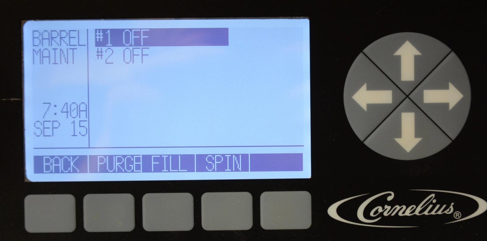
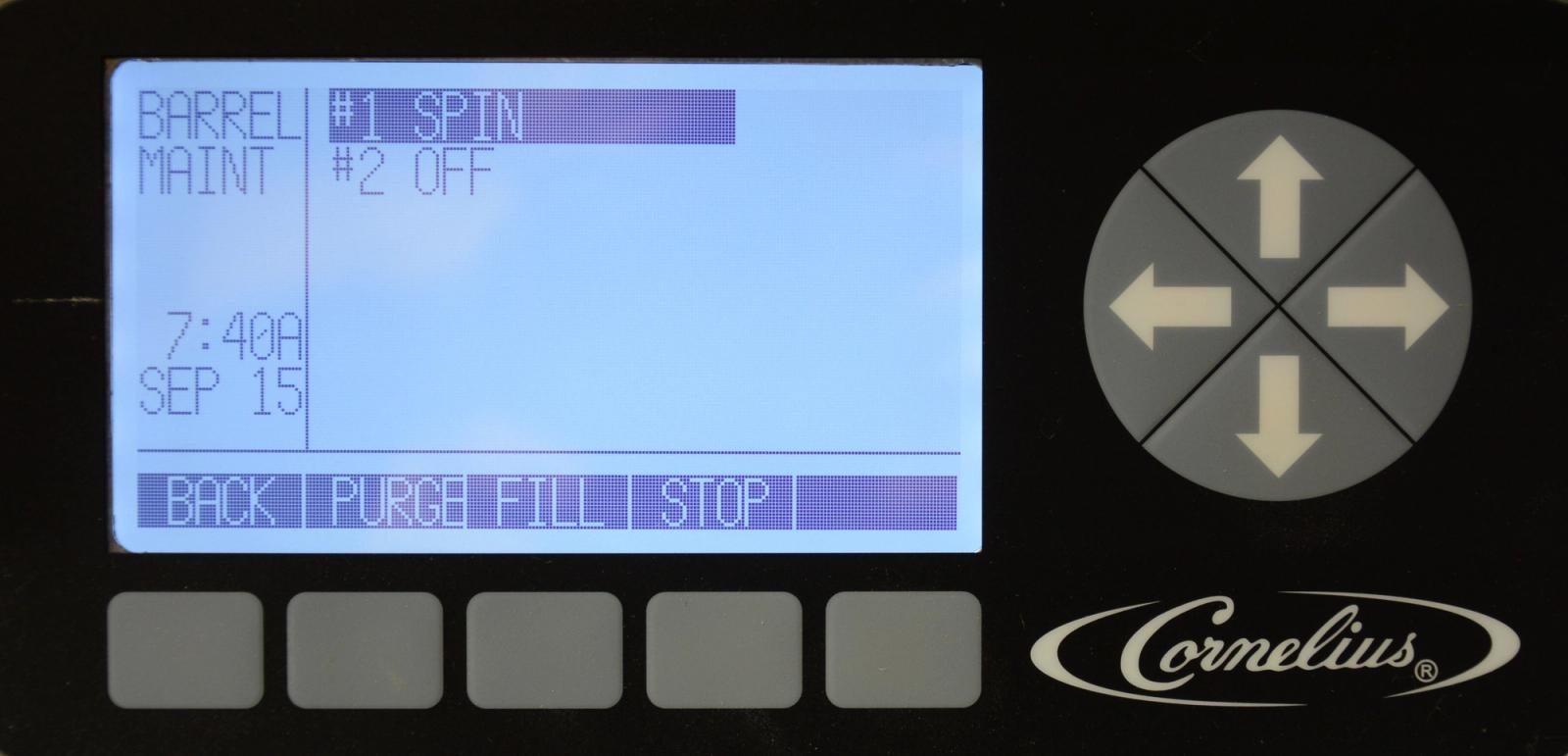
The Barrel Maintenance menu allows the service technician to PURGE, FILL, and SPIN as needed and these options are used for maintenance and service. As a warning to the technician, the "Do Not Drink" status indicators are illuminated on the barrels when entering the Barrel Maintenance menu.
Note: The maintenance menu is only available to service personnel or other authorized users, if security is enabled.
-
Barrel Maint - Purge
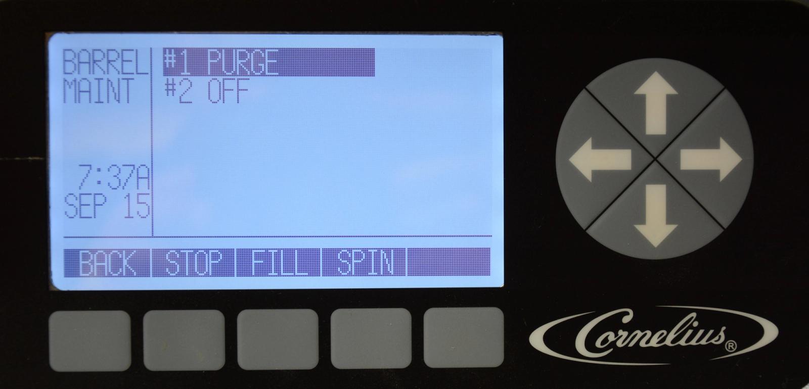
Purge is used to remove product from the barrel. Use the arrows to highlight the desired barrel.
Press the PURGE button at the bottom of the display and place a container under the barrel dispensing valve. Open the dispensing valve and dispense all the product from the barrel, the barrel will not refill while in purge mode. As the product level lowers in the barrel, partially close the valve to avoid spurting. When the barrel is completely empty, close the dispensing valve and press the STOP button to turn off purge mode.
-
Barrel Maint - Fill
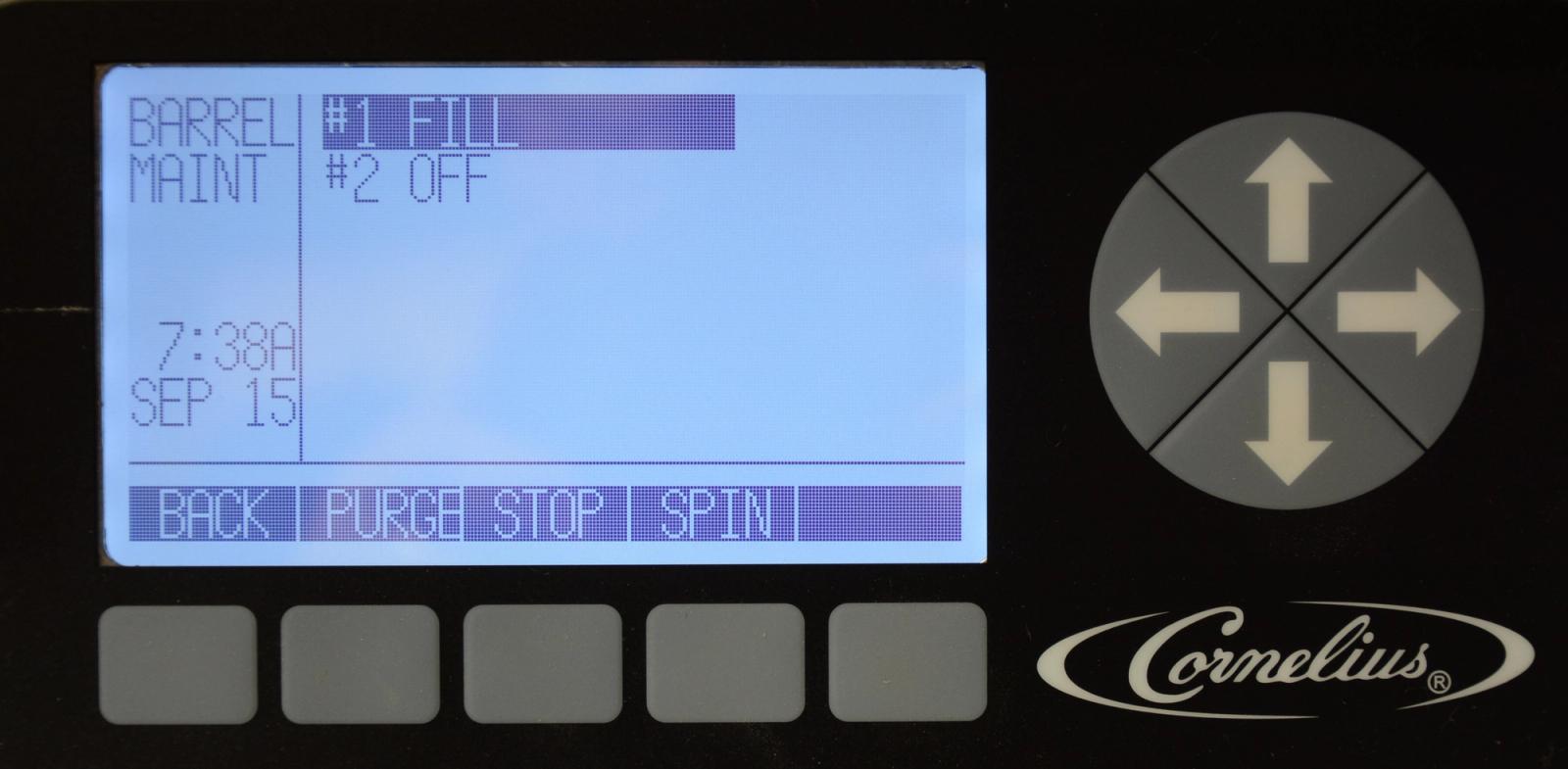
** Make sure the three-way valve is in BRL position**
Use the arrows to highlight the desired barrel. Press the FILL button at the bottom of the display to fill the highlighted barrel. As the barrel fills, the barrel pressure sensor shuts off the barrel at a pressure of 28 psi. When the fill completes, intermittently slowly open and close the relief valve to bleed CO2 from the barrel and fill the barrel approximately half way between the relief valve and the top of the barrel. Press the STOP button at the bottom of the display to stop the fill.
-
Barrel Maint - Spin
Use the arrows to highlight the desired barrel. Press the SPIN button at the bottom of the display. The drive motor for the selected barrel will come on and only spin the beater bar and scrapper blades, no refrigeration will come on for the barrel. Multiple barrels can be turned on at one time for this function. Pressing the stop button will stop the motor.
-
Introduction
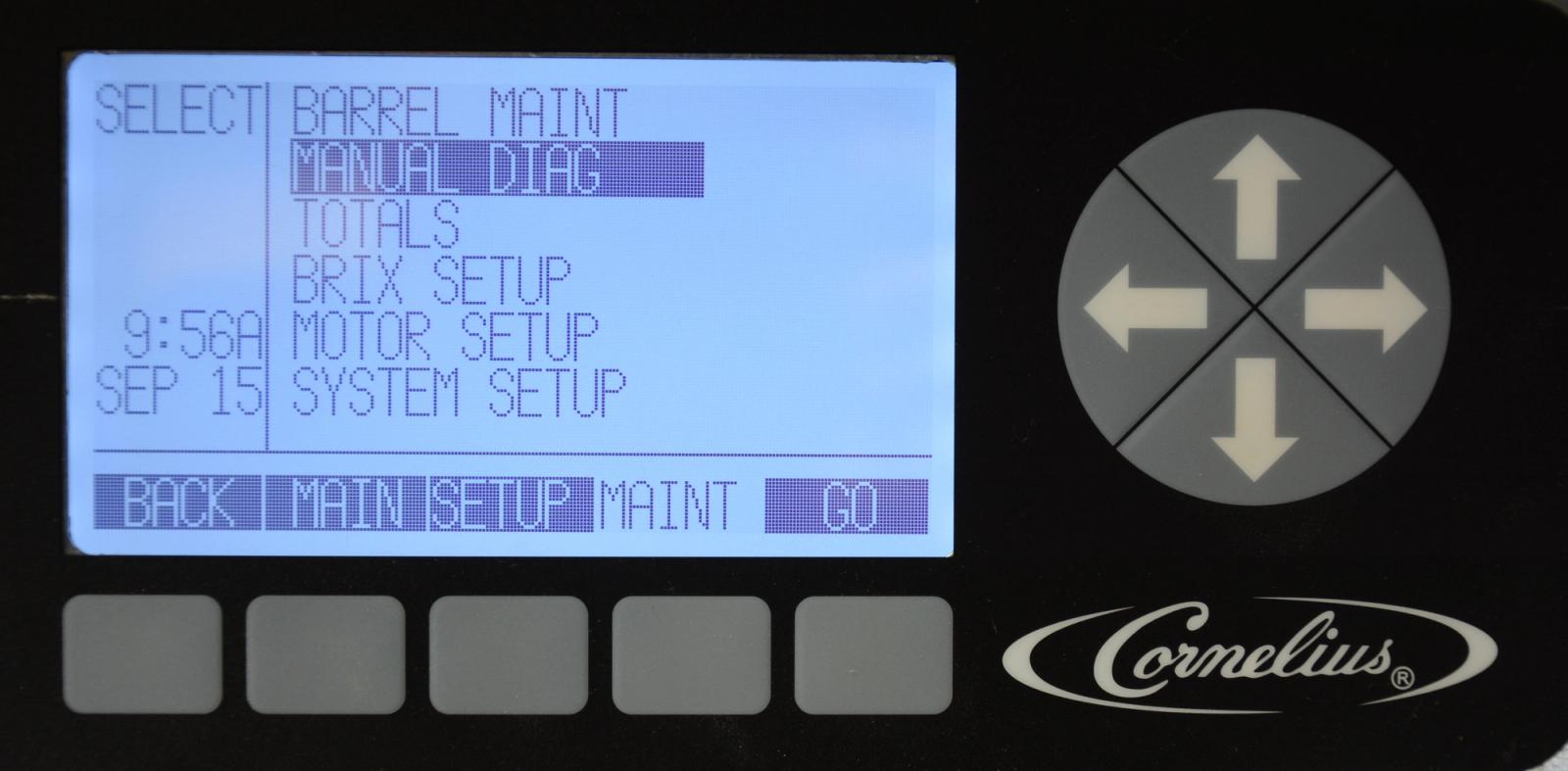
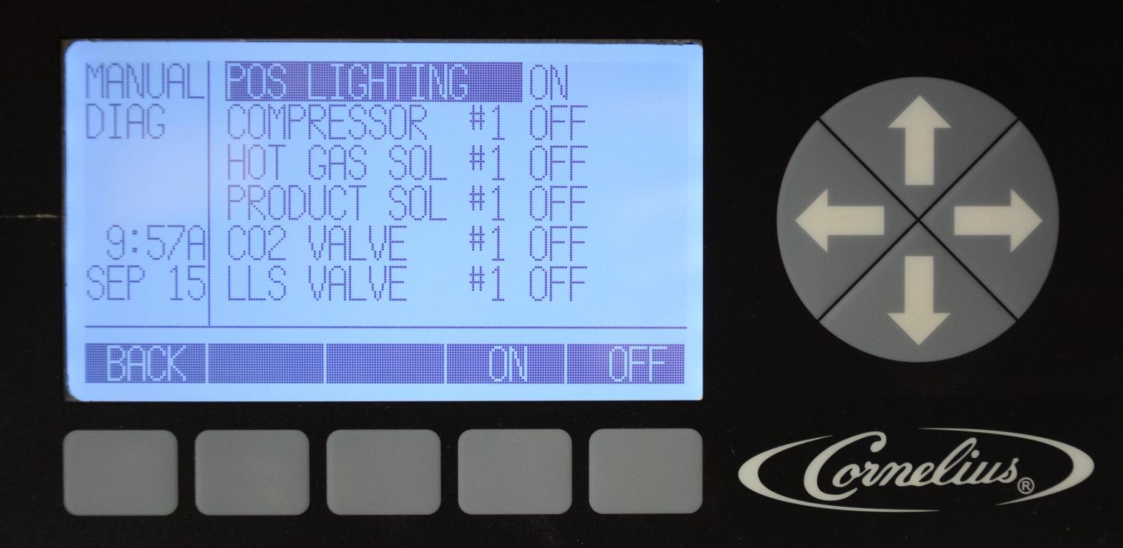
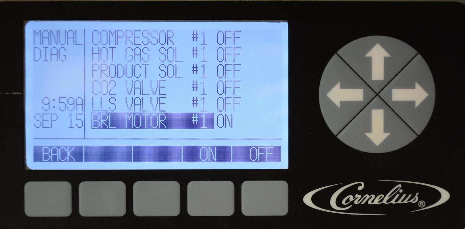
The Manual Diagnostic menu is used for troubleshooting and testing the system on a component basis. It allows the service technician to turn individual components of the Viper on and off for troubleshooting purposes. To move between one set of barrel parameters to the next, press the arrow keys. This moves the highlight to the first entry of the second barrel, etc. Pressing the BACK button returns the display to the Main menu and turns off all the active loads. All barrels and the POS lighting will turn off when in diagnostics.
NOTE: to avoid damage by deadheading the compressor, ensure that brl one LLS is working properly. Components stay activated for 30 seconds and will automatically turn off when you exit the menu.
-
Manual Diagnose – POS Lighting
This selection in the manual diagnostics menu turns the Point-Of-Sale lighting on and off.
-
Manual Diagnose – Compressor
This selection in the manual diagnose menu turns just the refrigeration compressor on and off. LLS for barrel 1 will activate at the same time to avoid deadheading.
Note:
Do not leave compressor turned on for extended period as damage may occur.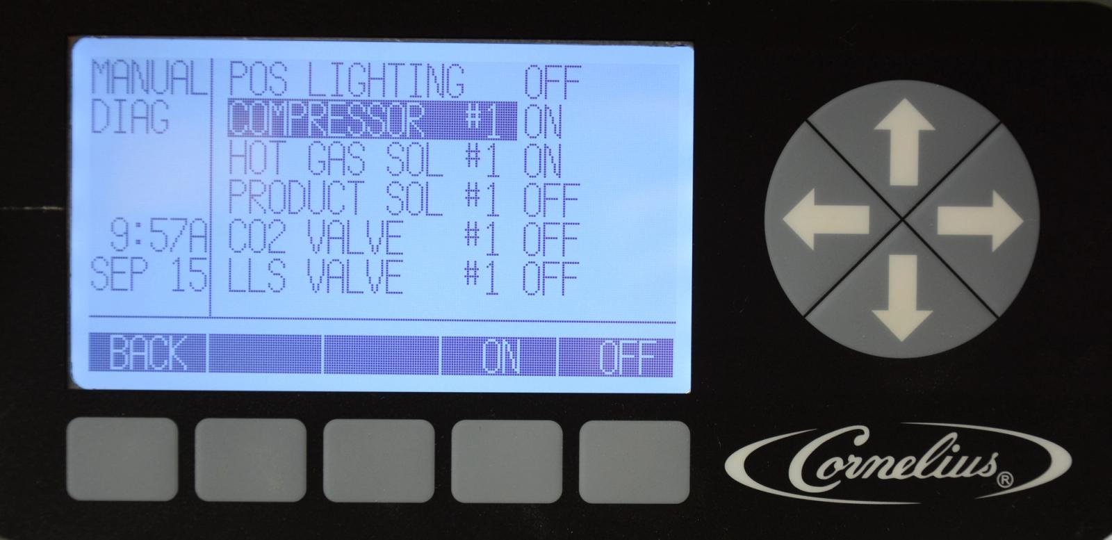
-
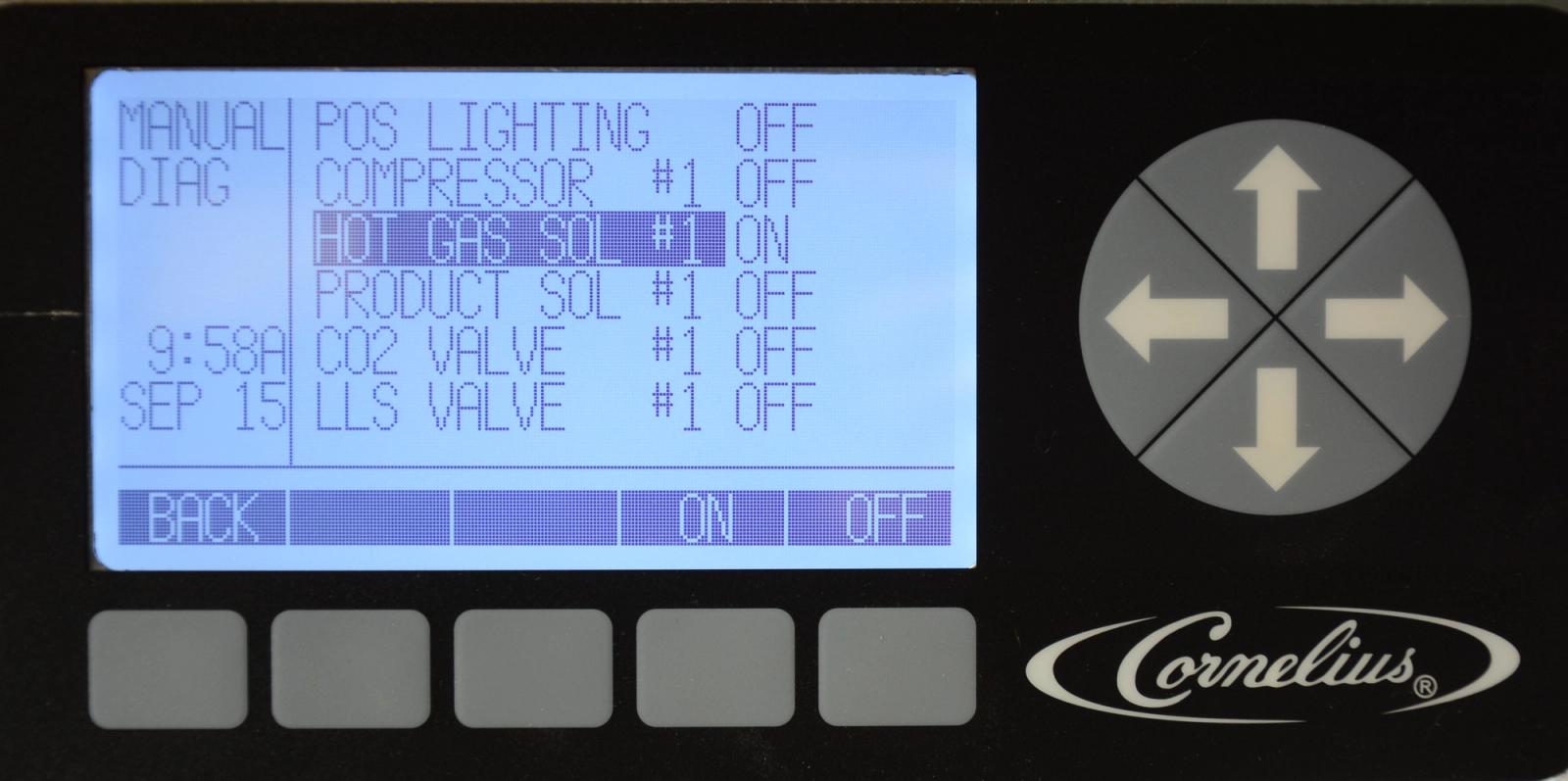
Manual Diagnose – Hot Gas Solenoid
This selection in the manual diagnostics menu opens and closes the hot gas solenoid for one barrel.
To move between one set of barrel parameters to the next, press the up and down arrow keys until you reach the next or previous barrel. This moves the highlight to the first entry of the second barrel, etc.
-
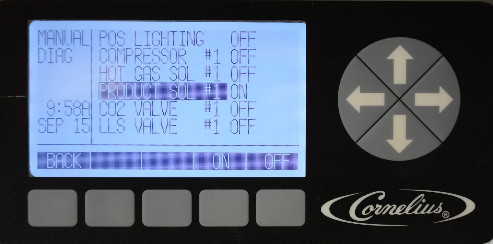
Manual Diagnose – Product Solenoids
This selection in the manual diagnose menu opens and closes the product (water and syrup) solenoids and valves for a barrel. To move between one set of barrel parameters to the next, press the up and down arrow keys until you reach the next or previous barrel. This moves the highlight to the first entry of the second barrel, etc.
-
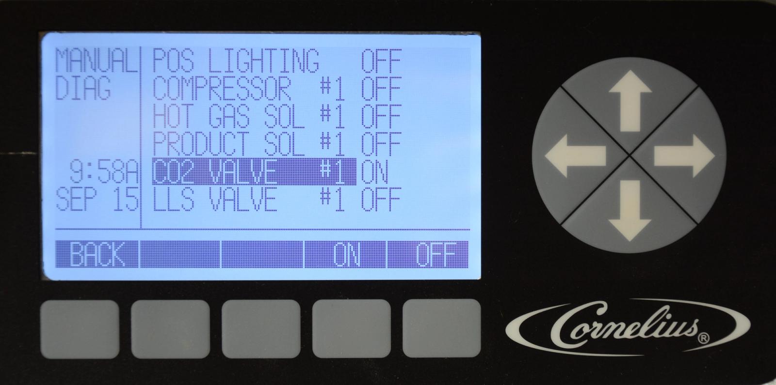
Manual Diagnose – CO2 Solenoid
This selection in the manual diagnose menu opens and closes the CO2 solenoid for a barrel. To move between one set of barrel parameters to the next, press the up and down arrow keys until you reach the next or previous barrel. This moves the highlight to the first entry of the second barrel, etc.
-
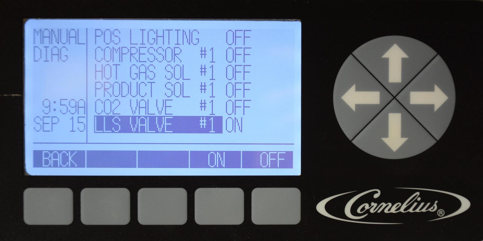
Manual Diagnose – Liquid Line Solenoid
This selection in the manual diagnose menu opens and closes the Liquid Line solenoid for refrigerant for a barrel.
To move between one set of barrel parameters to the next, press the up and down arrow keys until you reach the next or previous barrel. This moves the highlight to the first entry of the second barrel, etc.
-
Manual Diagnose – Barrel Motor
This selection in the manual diagnose menu turns a barrel drive motor on and off.
To move between one set of barrel parameters to the next, press the up and down arrow keys until you reach the next or previous barrel. This moves the highlight to the first entry of the second barrel, etc.
-
Totals
The Totals menu shows the cumulative run time of the system, components of the system or an error. Some individual items may be reset by highlighting the item and pressing the RESET button. The RESET button is only displayed for items that can be reset, such as hours since the motor seal was changed or the number of compressor cycles. Pressing the BACK button returns to the Choose menu and saves the changes. To move between one set of barrel parameters to the next, press the up and down arrow keys until you reach the next or previous barrel. This moves the highlight to the first entry of the second barrel, etc.
Totals table (Display | Value format | Description):
- POWER ON | HHHHH:MM | Shows how long the machine has been powered up
- SLEEP | HHHHH:MM | Shows how long the machine has been in sleep mode
- SYSTEM ERROR | HHHHH:MM | Shows how long the machine has had a system error
- COMP RUN #1 | HHHHH:MM | Shows how long the compressor has been running since the last reset
- COMP CYCLES #1 | ######## | Shows the number of compressor cycles since the last reset
- BARREL REFG #1 | HHHHH:MM | Shows how long the barrel has been in refrigeration mode
- MOTOR ON #1 | HHHHH:MM | Shows how long the motor has been running on a specific barrel
- MOTOR SEAL #1 | HHHHH:MM | Shows how long it has been since the motor seal was inserted on a specific barrel
- DEFROST #1 | HHHHH:MM | Shows how long the barrel has been in defrost mode
- FILL CYCLES #1 | ######## | Shows the number of times the barrel has filled with product
- SYRUP RUN #1 | HH:MM:SS | Shows how long the syrup solenoid has been open
- SYRUP OUT #1 | HHHHH:MM | Shows how long the syrup has been out
- ERROR #1 | HHHHH:MM | Shows how long the barrel has had an error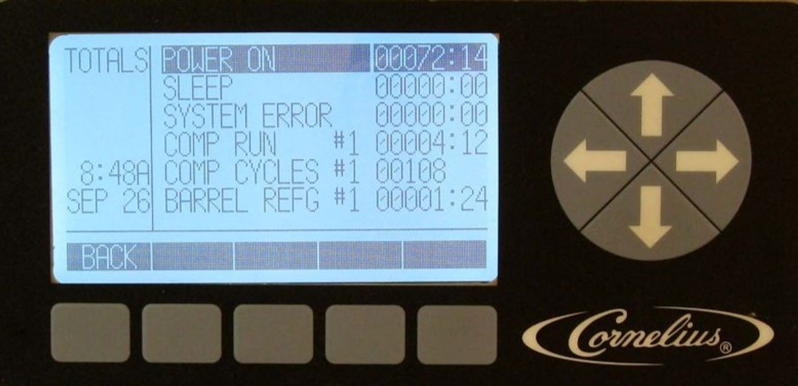
-
Brix Setup
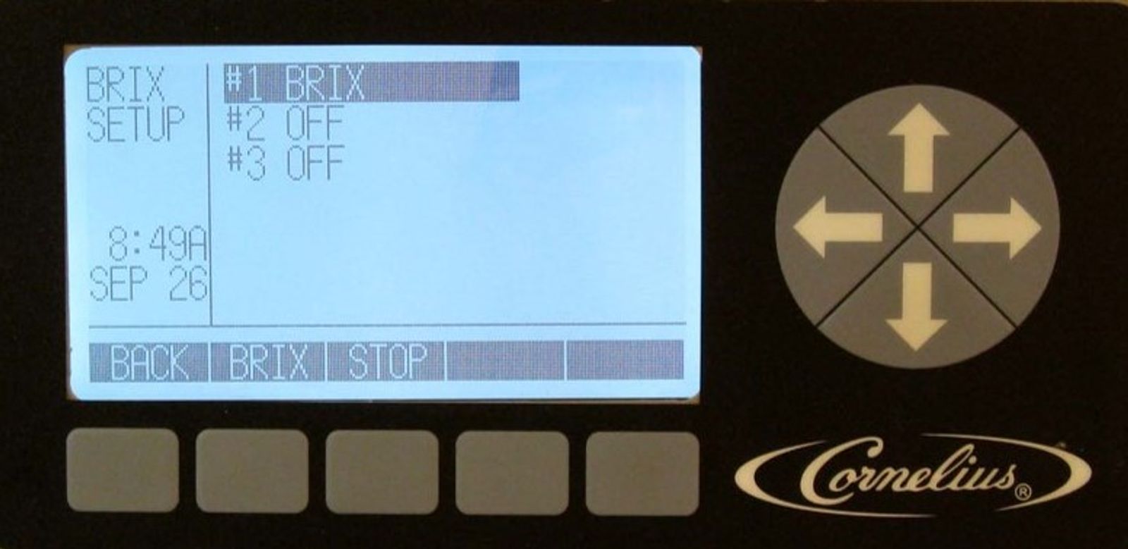
Checking the Brix determines the amount of sugar in the product. The higher the brix the more sugar, the lower the brix the less sugar.
The BRIX SETUP menu is located in the MAINT menu. The Viper is programmed for a three second dispense so that brix comparisons can be made between samples. Start by using the up and down arrows to highlight the barrel to be brixed. Next, turn the three-way valve down to brix position and remove the end cap of the sample tube. While holding the tube in a container press the brix button and collect and discard the first three samples. Then using a refractometer measure brix from the fourth sample.
-
Introduction
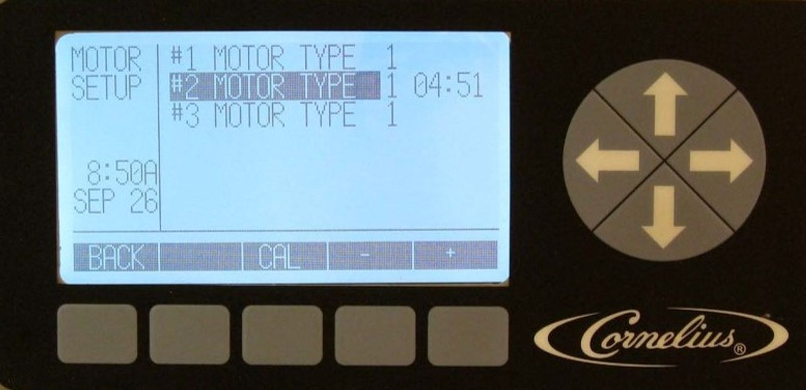
This menu allows you to select different motor types for each barrel in the unit and run the calibration procedure on that motor. From the maintenance screen Highlight MOTOR SETUP and press button below GO.
Ensure that the motor type matches the model of unit. Use the arrows to highlight the desired barrel and press the + or - buttons to select the proper motor type. Motor setup is done at the factory and does not need to be changed but should be checked and verified.
Motor type table (Model | Motor Type):
- All 60 Hz | 1
- All 50 Hz | 2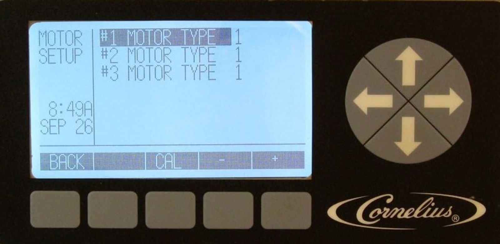
-
Motor Setup - Calibrate
Calibration establishes a new baseline for the motor assembly. This allows the system to determine proper viscosity settings for the new motor. It is VERY IMPORTANT that calibration be performed when the product in the barrel is in a 100% liquid state. There can be no ice in the barrel or on the beater bar. Press the CAL button at the bottom of the Motor Setup menu to start the calibration process. The calibration cycle continues for five (5) minutes to allow the gearbox to stabilize at temperature and ensure correct calibration based off of the liquid product.
-
Introduction
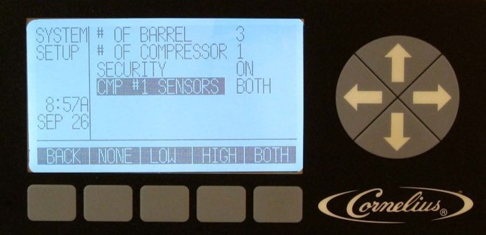
From the maintenance screen, Highlight SYSTEM SETUP and press button below GO.
The System menu is used during production to set up the unit parameters. It also allows the technician to view the number of barrels, the number of compressors and the number of pressure sensors present in the system
NOTE: Changing these values to a number that doesn't match the physical number of items in the system generates errors or turns off some of the equipment present in the system. When the individual fields are highlighted, the display buttons change.
System setup table (Option | Button 2 | Button 3 | Button 4 | Button 5):
- # of barrels | | | - | +
- # of compressors | | | - | +
- Security | | | OFF | ON
- Compressor sensors | NONE | LOW | HIGH | BOTH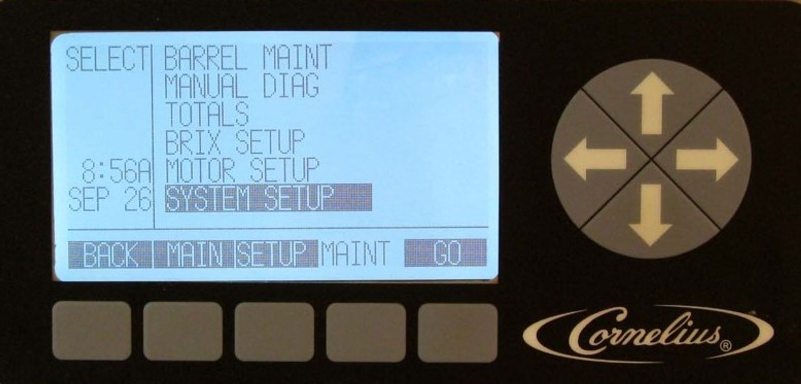
-
System -
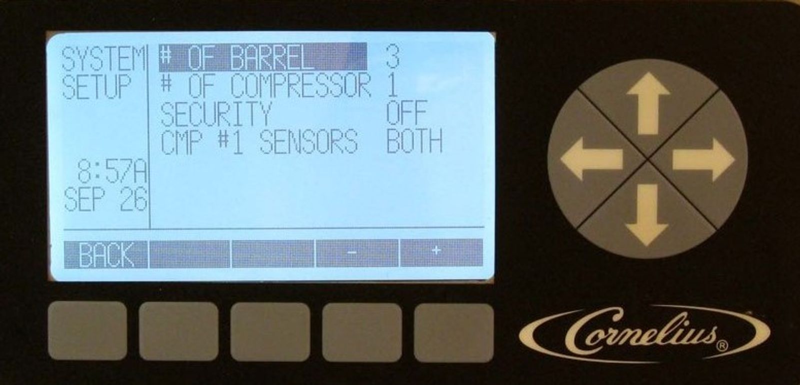
This selection in the system menu shows the number of barrels and should only be set for number of barrels in the Viper.
Note: the Viper can sometimes convert to two barrels after electrical surges and will only display two barrels on the status screen.
-
System -
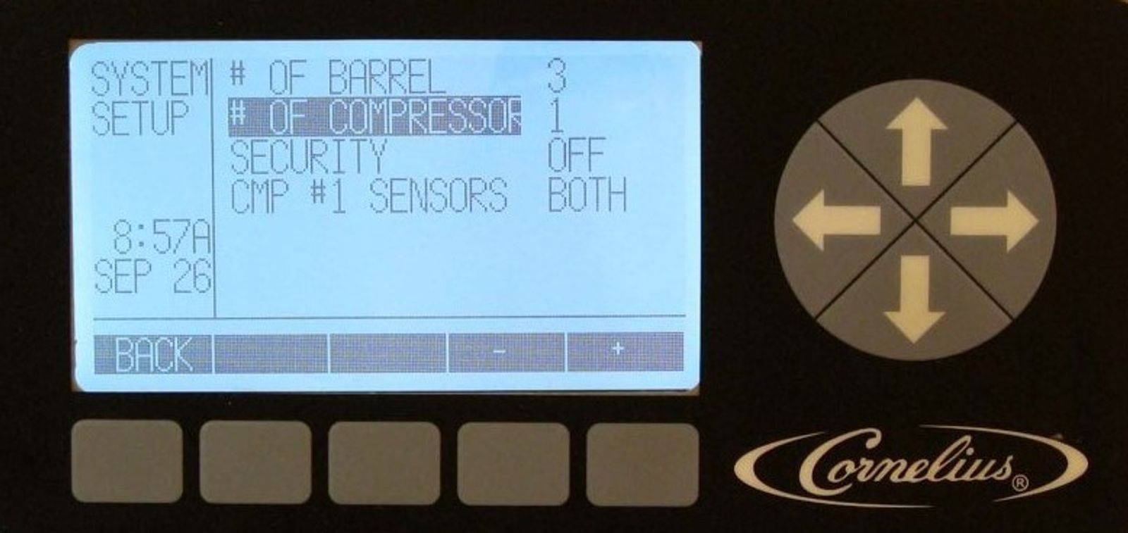
This selection in the system menu shows the number of compressors. Currently this number is fixed at one and cannot be changed.
-
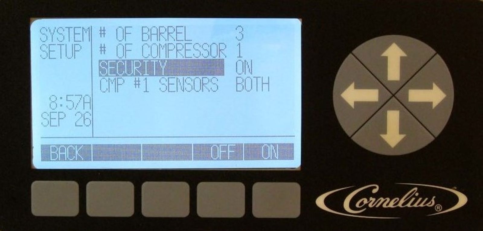
System - Security
This selection in the systems menu allows the user to turn security on or off and keep unauthorized personnel from accessing the MAINT menu. When security is turned on, users can only access the Main and Setup menus. Pressing the far Left and Right buttons (Buttons 1 and 5) on the bottom of the display simultaneously and holding them for approximately five (5) seconds unlocks the Security menu. If security is left ON in the System menu the system will time out or when the user goes back to the Main menu and the security will be re-activated. To disable security, access the System menu, highlight Security and press the OFF button.
-
System – Compressor
Pressure sensors allow the technician to view the high and low-side refrigeration pressures in the Viper without having to connect external gauges to the system. When the pressure sensors selection is highlighted, pressing the NONE button removes the pressure readings from the Unit Data screen, If LOW is selected, only the low pressure reading is displayed and if HIGH is selected, only the high pressure reading is displayed and if BOTH is selected the low and high pressure readings are displayed
The low side pressure sensor is used to monitor compressor reversal. The number of sensors in the unit are set at the factory and should not be changed.