Connections
Viper — Installation
-
Water Supply Volume
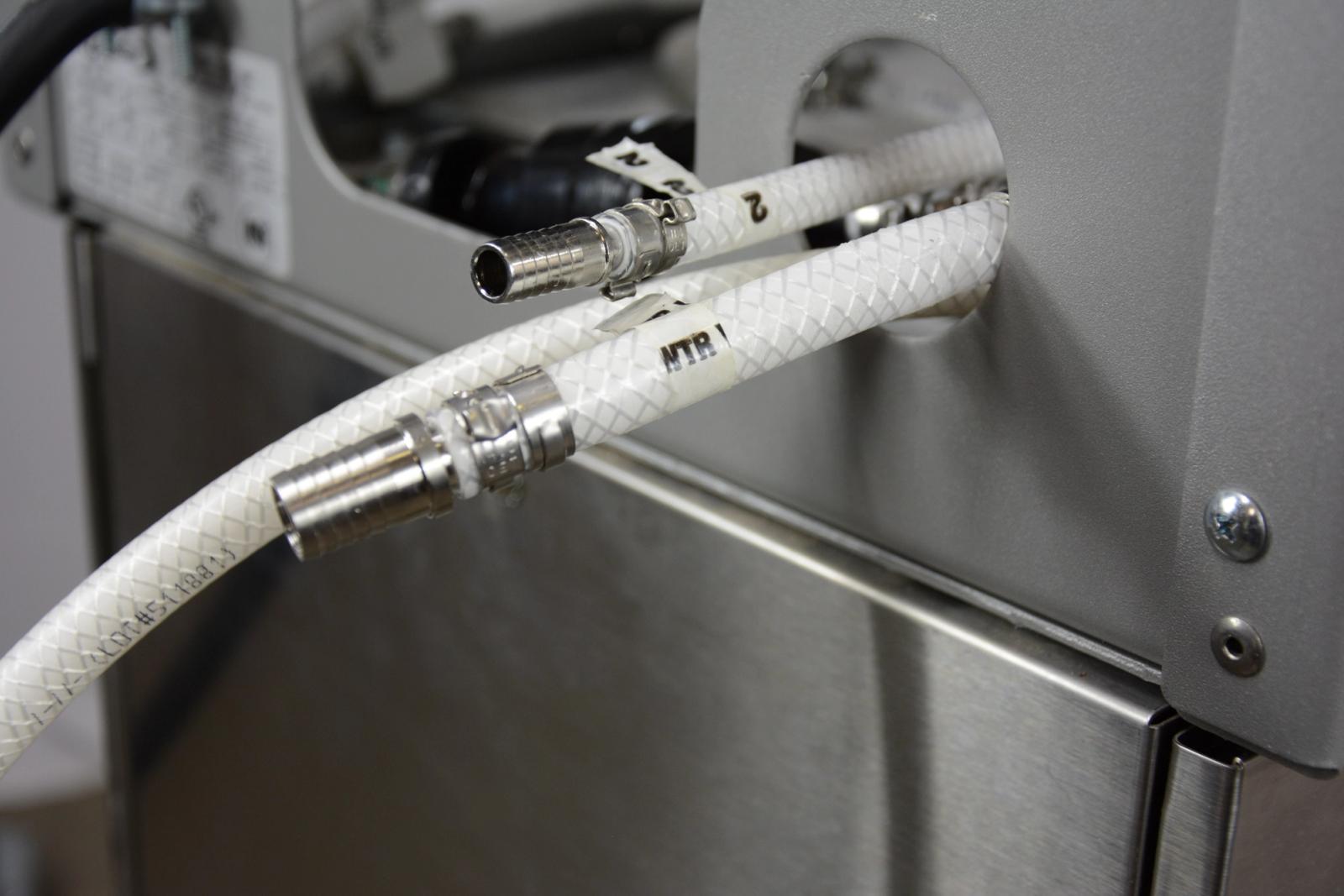
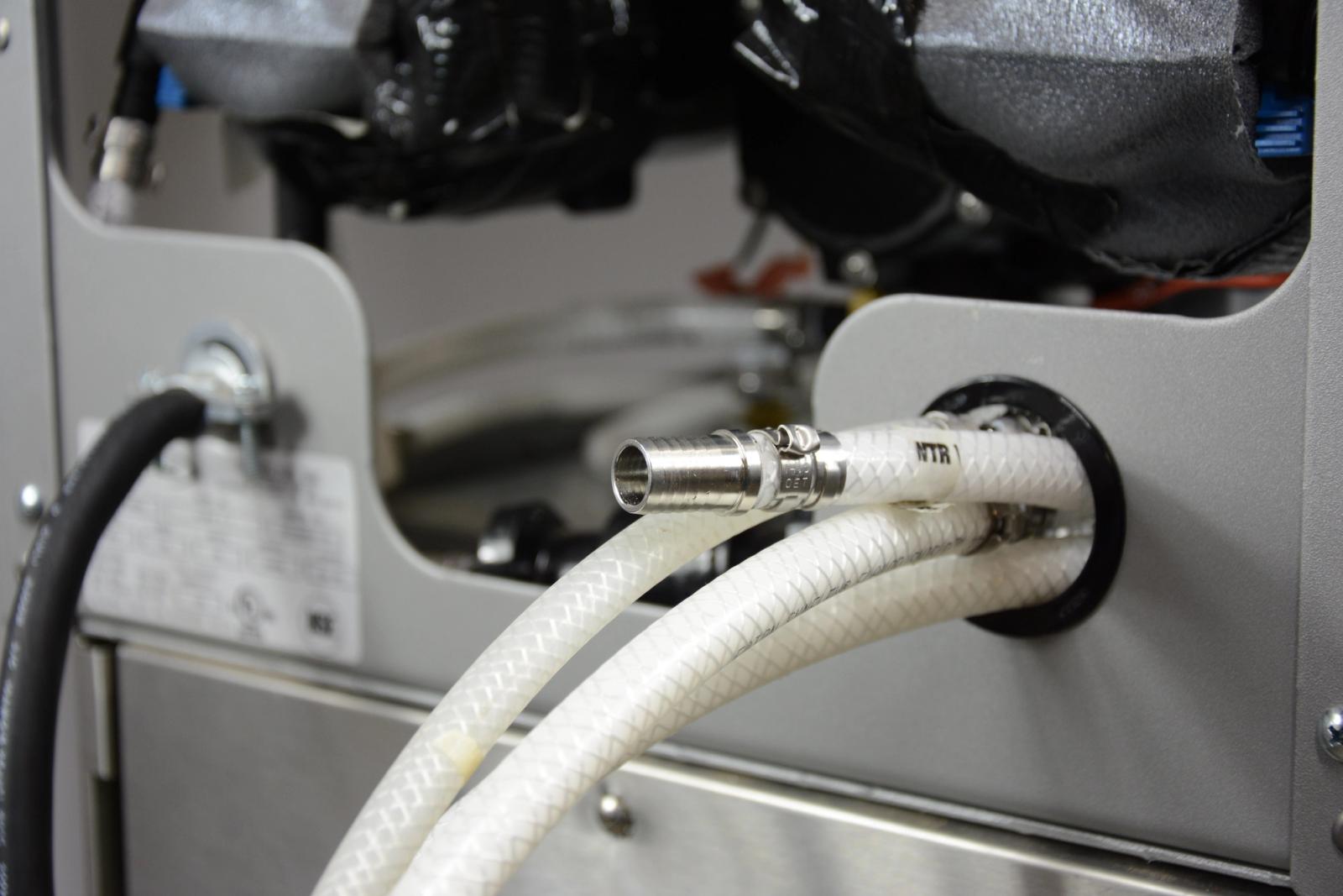
The Viper water supply inlet is equipped with a 1/2” barbed fitting. Water supply lines are required to be ½ ID tubing along with appropriate sized connections. Two and three flavor Vipers require 100 GPH while four flavor Vipers require 150 GPH. As a general rule, if you can fill a 5 gallon bucket in 3 minutes you have enough water flow to be at 2.5 GPM. The incoming water flow should maintain a minimum of 65 psig dynamic pressure. If water pressure it low, the use of a water booster should be used. You must install a 50psi-65psi WPR prior to the Viper water inlet.
-
Water Supply filtration
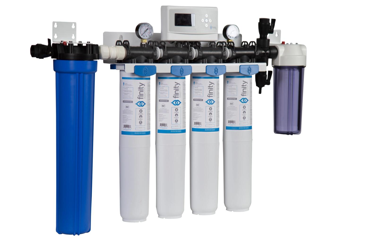
The use of a pre filter to remove large sediment followed by carbon filters to remove taste and odor is recommended. DO NOT SUPPLY THE VIPER WITH SOFT OR DESCALED (RO) WATER, AS IT WILL PREVENT PROPER CARBONATION.
-
CO2 Supply
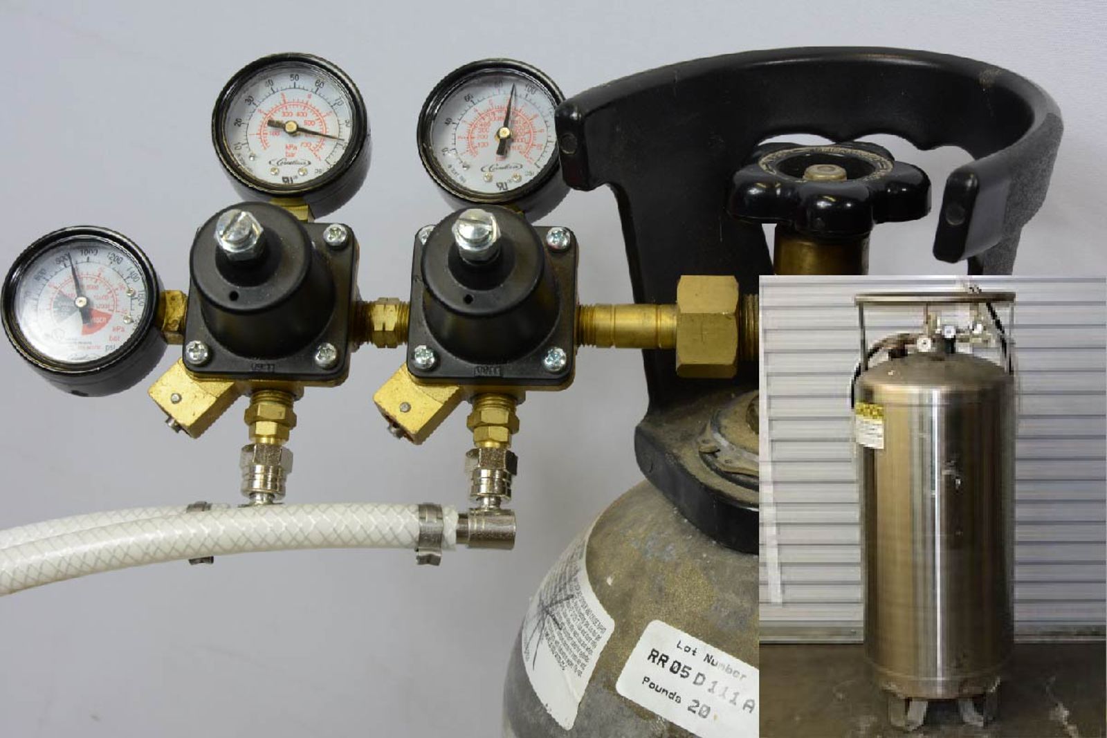
There are two CO2 delivery systems available, a high pressure cylinder or a low pressure bulk tank. A high pressure cylinder requires a primary regulator. A low pressure bulk system will have a regulator as part of the bulk tank. Either CO2 systems output regulator should be set to supply between 90psi to 120psi to the Co2 secondary regulators. The Viper is shipped with two secondary Co2 regulators; one that is dedicated to the viper and one that is dedicated to the FCB BIB pumps, both are set at 75 ±1 psig. All Co2 tubing is required to be 3/8” I.D. Also secondary regulators should be easily accessible and within 6 feet of the Viper and BIB rack. Do not turn on the CO2 supply until the commissioning of the Viper is performed.
CO2 to the unit must have two 75psi regulators - one for the BIBs and another for the unit. These regulators should both be initially set to “0” and gradually turned up to 75psi after the CO2 has been turned on.
Not doing this will push 110psi of CO2 into the 75psi regulator, then into the 30psi regulator potentially causing the expansion tanks to fail. The unit is made to gradually turn on the CO2
Note: Label the secondary Co2 regulators as Viper and FCB BIB for identification purposes.
-
Syrup Supply
The Viper syrup supply inlets are equipped with a 3/8” barbed fitting. The use of 3/8ID tubing with appropriate sized connections for the syrup lines from the backroom BIB rack assembly to the Viper is required. Do not turn on the syrup supply until the commissioning of the unit.